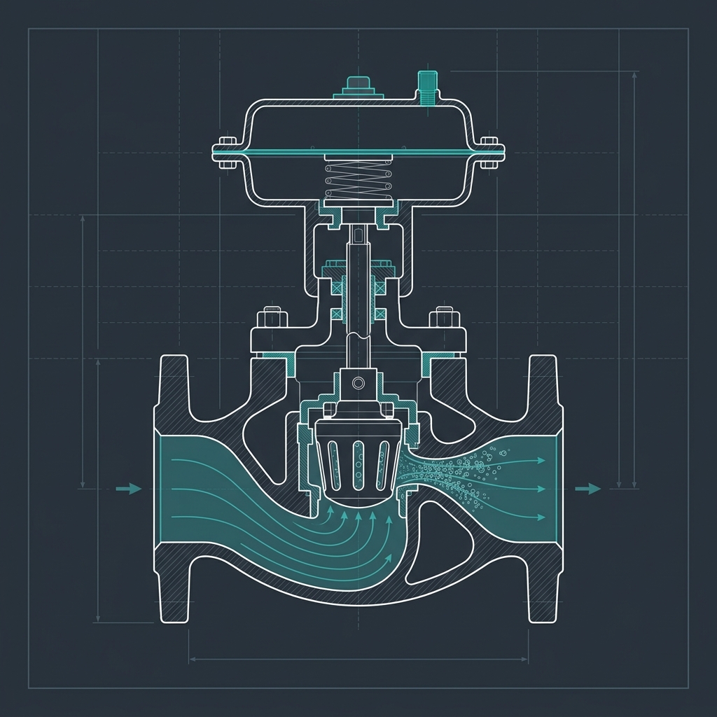
# Control Valve Sizing: Why the Cv You Calculate Is Never the One Installed
Process control valves regulate fluid flows by adjusting their opening areas. In the metric system, valve capacity is defined by Kv (expressed in m^3/h of water at a pressure drop of 1 bar). The imperial equivalent is Cv (expressed in GPM at 1 psi pressure drop). The conversion factor between the two standard coefficients is:
Cv = 1.156 * Kv
In this guide, we review the calculations for sizing liquid control valves using metric units and evaluate common pitfalls in selection.
# 1. Liquid Sizing Formula (Metric)
For non-cavitating liquid service, the required Kv is calculated using:
Kv = Q * sqrt( SG / delta_P )
Where:
- Kv = Valve flow coefficient (m^3/h).
- Q = Volumetric flow rate (m^3/h).
- SG = Specific gravity of fluid (dimensionless, water = 1.0).
- delta_P = Pressure drop across the valve (bar) = P_inlet - P_outlet.
Once Kv is calculated, engineers convert it to Cv to match manufacturer catalog sheets if they utilize imperial models.
# 2. Worked Example
A transfer line feeds methanol (SG = 0.79) to a distillation column at a rate of 12 m^3/h (200 L/min). The available pressure drop across the control valve is 1.5 bar.
# Step 1: Calculate Required Kv
Kv = 12 * sqrt( 0.79 / 1.5 )
Kv = 12 * sqrt( 0.526 ) = 12 * 0.725 = 8.7 m^3/h
# Step 2: Convert to Cv
Cv = 1.156 * Kv = 1.156 * 8.7 = 10.1
# Step 3: Selection Rule
To maintain stable control, the valve should operate between 20% and 80% open under normal conditions. We select a valve with a maximum Cv of 15 (equal percentage characteristic) to provide a safety margin.
# 3. Reference Standards
- ISA-75.01.01: Flow Equations for Sizing Control Valves.
- IEC 60534-2-1: Industrial-process control valves - Part 2-1: Flow capacity.
# 🛠️ Interactive Engineering Tool
To perform calculations related to this topic, access our interactive engineering tool: Pipe Line Sizing Calculator.
# Applicable Engineering Standards & Codes Used
The engineering methodologies, design correlations, and safety criteria detailed in this article adhere to the following international standards and industry codes:
- ASME B31.3: Process Piping Code
- API RP 14E: Recommended Practice for Design and Installation of Offshore Production Platform Piping Systems
- Hydraulic Institute Standards (HI 1.3, HI 2.3) for Centrifugal and Positive Displacement Pumps: Hydraulic Institute Standards (HI 1.3, HI 2.3) for Centrifugal and Positive Displacement Pumps
- ISO 5167: Measurement of Fluid Flow by Means of Pressure Differential Devices