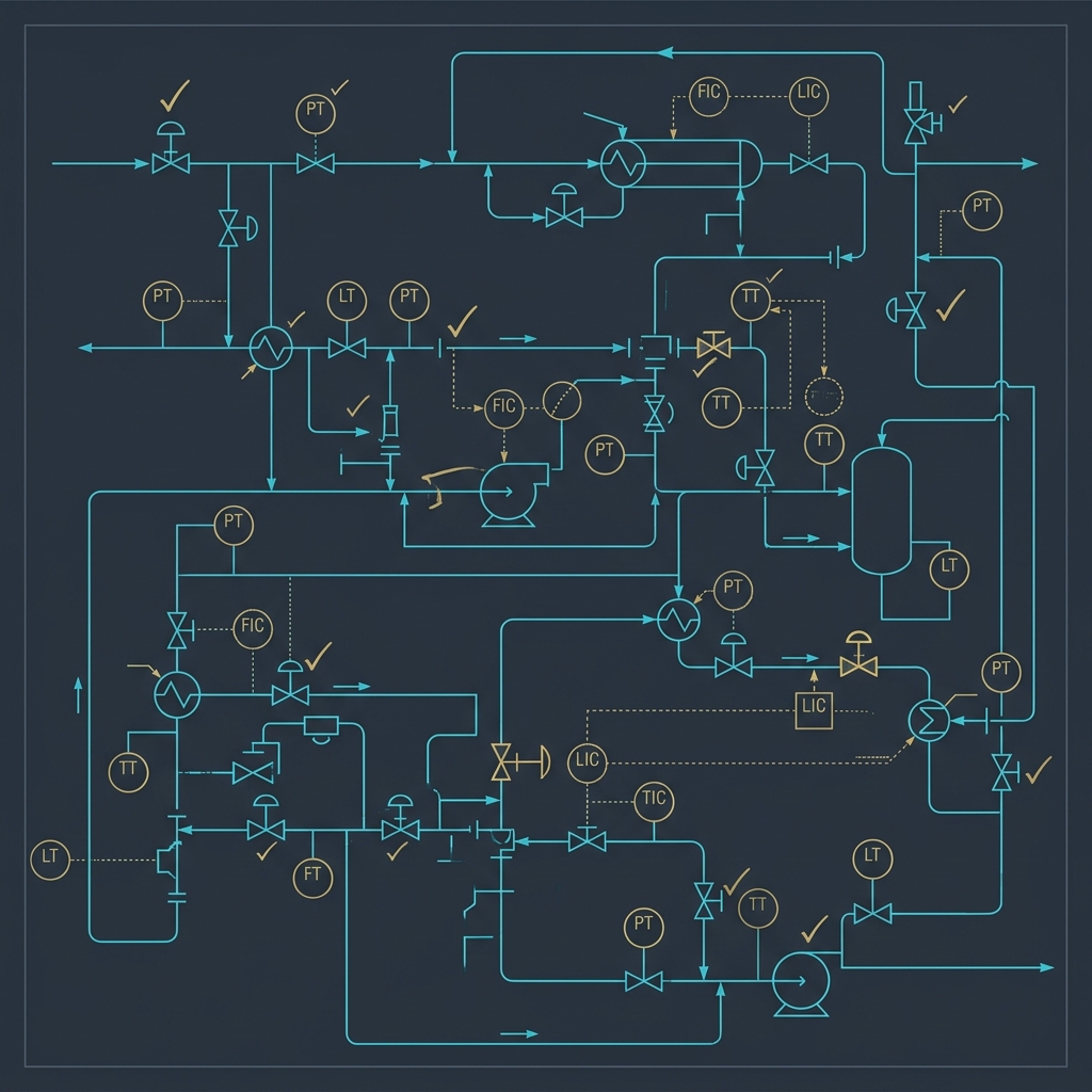
# Pharma P&ID Review Checklist: 50 Things Most Engineers Miss
A Piping and Instrumentation Diagram (P&ID) is the primary technical blueprint of a pharmaceutical or chemical process plant. It maps the physical process lines, valve placements, instruments, control loops, safety relief valves, and utility interfaces. A single missing check valve or misaligned instrument can lead to batch cross-contamination, validation failures, or explosive runaway hazards.
In this guide, we review why P&IDs are critical, examine their significance in the plant engineering lifecycle, and present a comprehensive 50-point checklist specifically tailored for pharmaceutical chemical manufacturing.
# 1. Why a P&ID?
A P&ID is the central document that coordinates all engineering disciplines during process plant design. While a Process Flow Diagram (PFD) captures the thermodynamics and heat/mass balances of a process, the P&ID details the physical implementation. It shows exactly how piping, valves, and instruments must be installed to operate the plant safely and efficiently.
# 2. Significance in the Project Lifecycle
P&IDs are utilized across the entire lifecycle of a chemical manufacturing facility:
- Detailed Design & Procurement: Piping designers use the P&ID to create 3D piping layouts, and instrumentation engineers use it to compile the instrument index and purchase specifications.
- Control System Programming (DCS/PLC): Automation engineers use P&ID control loops (e.g., cascade PID loops) and interlock line designations to write the DCS operating software.
- Process Safety & HAZOP: A HAZOP study is performed by stepping through the P&ID node-by-node, analyzing deviations (such as no flow, reverse flow) to identify safety gaps.
- Commissioning & Qualification: Commissioning teams walk down the physical plant lines using the P&ID to verify that construction matches the design intent before the first solvent batch is charged.
# 3. The 50-Point Pharma P&ID Review Checklist
Below is the complete 50-point checklist divided into functional design categories:
# Category A: Piping, Slope & Sanitary Design (cGMP)
- Line Slopes: Check that all process lines handling product or CIP fluids have a minimum slope of 1:100 (1%) to ensure complete self-drainage.
- Dead-Leg Limits: Verify that dead-legs on sanitary water loops (PW/WFI) and product lines do not exceed the 2D (two-pipe-diameter) rule.
- Reduction Concentric vs. Eccentric: Ensure eccentric reducers (flat side down) are used on pump suction lines to prevent vapor pocket cavitation.
- MOC Continuity: Confirm that the Material of Construction (MOC) changes (e.g., from Glass-lined steel to Hastelloy) are explicitly labeled with flange breaks.
- High Point Vents: Are high point vents shown at all line loops to facilitate initial system purging and hydro-testing?
- Low Point Drains: Are low point drains shown at all piping pockets to allow complete solvent extraction during product changeover?
- Hose Connections: Are temporary utility hose connections (such as nitrogen purging stations) equipped with double block-and-bleed valves?
- Sight Glasses: Check that sight glasses are placed on the gravity drain discharge lines of separators to allow operators to visually verify phase boundaries.
- Flexible Hoses: Ensure that flexible transfer hoses are labeled with pressure ratings and length limitations.
- Sample Valves: Verify that sanitary flush-mounted sample valves are installed directly on reactor bottom outlets, minimizing dead volume.
# Category B: Valve Placements & Configurations
- Valve Styles: Ensure diaphragm valves are specified for sanitary product-contact lines, and ball/plug valves are restricted to utilities.
- Double Block and Bleed (DBB): Verify that DBB valves are placed on solvent headers to prevent cross-contamination between batches.
- Check Valves (Non-Return): Are check valves installed on all utility headers (nitrogen, compressed air) to prevent process solvents from backing up into utility lines?
- Pump Isolation: Check that suction and discharge isolation valves are shown for all transfer pumps.
- Jacket Isolation: Verify that isolation valves are shown on both the inlet and outlet utility cooling lines of reactor jackets.
- Failsafe Valve Actions: Confirm that the failsafe state of all control valves is explicitly labeled (Fail Open - FO, Fail Closed - FC, or Fail Last - FL).
- By-pass Valves: Ensure that bypass globe valves are placed around critical control valves to allow manual operation during maintenance.
- Control Valve Sizing: Check that reducers are shown around control valves (since control valves are typically smaller than line sizes).
- Breather Valves: Are vacuum-pressure breather valves shown on atmospheric storage tanks to prevent tank collapse during pump-out?
- Three-Way Valves: Ensure three-way valves are shown on the outlet of sanitization loops to divert off-spec rinse water to waste drains.
# Category C: Instrumentation & Control Loops
- Redundant Probes: Verify that dual (1oo2) temperature transmitters are specified for reactors handling highly exothermic reactions.
- Thermowells: Ensure all temperature sensors in corrosive chemical environments are shown inside protective thermowells.
- Pressure Indicators (PI): Are pressure indicators placed on both the suction and discharge lines of pumps to facilitate troubleshooting?
- Flow Meter Straight Runs: Verify that flow transmitters (such as electromagnetic or coriolis) have sufficient straight-run pipe lengths labeled upstream and downstream.
- Level Transmitter Span: Check that level transmitters on reactors cover the entire vertical shell span, including the lowest impeller blade level.
- Differential Pressure (DP): Verify that DP indicators are shown across cartridge filters to monitor filter clogging.
- Interlock Designations: Ensure that safety interlock connections (e.g., tripping dosing feed valve XV-101 on high reactor temperature) are shown with dashed signal lines.
- Vessel Overfill Alarms: Are independent high-high level switches (LSHH) shown on storage vessels, separated from the primary level transmitter?
- Solvent Totalizers: Check that mass flow meters on solvent charge lines are linked to totalizer logic on the DCS.
- Agitator VFDs: Verify that Variable Frequency Drives (VFD) are shown on the reactor agitator motor symbol to allow speed control.
# Category D: Safety & Emergency Relief (DIERS)
- Rupture Disks Upstream of PSVs: Ensure rupture disks are installed upstream of pressure safety valves (PSVs) on corrosive vessels, protecting the valve internals from corrosion.
- Relief Discharge Headers: Check that PSV discharge lines are directed to a safe catch tank or scrubber system, not directly to the atmosphere.
- Relief Valve Isolation: If isolation valves are placed before relief valves, verify they are labeled as "Car Seal Open" (CSO) to prevent accidental closure.
- Flame Arrestors: Are flame arrestors shown on the vent lines of flammable solvent storage tanks?
- Nitrogen Blanketing: Verify that a continuous nitrogen blanket regulator is installed on reactors handling Class I flammable solvents.
- Emergency Drench Systems: Ensure emergency cooling utility bypass lines bypass the primary control valves to inject water directly in case of a power loss.
- Vacuum Break Valves: Check that vacuum breakers are installed on reactor headspace lines to prevent vacuum collapse during cold solvent charging.
- Thermal Relief Valves (TRV): Are TRVs shown on liquid-packed lines that can be blocked in by valves (e.g., jacket cooling water loops) to prevent thermal expansion overpressure?
- Scrubber Interlocks: Confirm that the exhaust fan on the reactor scrubber line is interlocked to the process solvent charge valves.
- Static Grounding Indicators: Verify that static grounding clamp monitors are shown at raw material charging stations.
# Category E: Utility Interfaces & Support Systems
- Steam Traps: Check that steam traps are shown at the low points of clean steam headers to prevent water hammer.
- Condensate Recovery: Are condensate return lines equipped with check valves to prevent backflow from the recovery header?
- HVAC Air Quality: Ensure that HVAC classifications (e.g., Grade C, Grade D cleanrooms) are marked on the cleanroom boundaries adjacent to open reactor manways.
- Cooling Water Flow Direction: Verify that cooling water enters at the bottom nozzle of the heat exchanger and exits at the top nozzle to ensure it remains flooded.
- Nitrogen Purging Points: Are nitrogen purge inlet nozzles located opposite the exhaust vent nozzle to ensure maximum sweep efficiency?
- CIP Return Pumps: Ensure CIP return lines are equipped with liquid-ring self-priming pumps to prevent foam buildup.
- WFI Loop Velocity: Check that the Water for Injection loop return line has a continuous flow indicator showing velocities above 1.5 m/s to prevent biofilm growth.
- Exhaust Vent Sizing: Are exhaust vent lines on reactor headers sized to handle the peak nitrogen purge flow rates?
- Waste Divert Valves: Are waste divert valves shown on utility lines to redirect contaminated water to effluent treatment plants?
- Utility Line Spec Breaks: Verify that spec break symbols are shown at the boundary where process piping interfaces with central utility piping.
# 4. Reference Standards Used
- ISA-5.1: Instrumentation Symbols and Identification.
- ASME BPE: Bioprocess Equipment Standard.
- ISO 14644: Cleanrooms and associated controlled environments.
# Applicable Engineering Standards & Codes Used
The engineering methodologies, design correlations, and safety criteria detailed in this article adhere to the following international standards and industry codes:
- ASME B31.3: Process Piping Code
- API RP 14E: Recommended Practice for Design and Installation of Offshore Production Platform Piping Systems
- Hydraulic Institute Standards (HI 1.3, HI 2.3) for Centrifugal and Positive Displacement Pumps: Hydraulic Institute Standards (HI 1.3, HI 2.3) for Centrifugal and Positive Displacement Pumps
- ISO 5167: Measurement of Fluid Flow by Means of Pressure Differential Devices