Back to Publications
Process Engineering4 min read

Sizing Relief Systems for Single-Phase & Flashing Two-Phase Flows (Part 3)

Kiran SeepanaSeptember 15, 202621 Views
Executive Summary & Scope

Sizing relief valves and rupture disks for liquid, choked gas, and flashing two-phase flow using HEM, HDI, and Leung Omega method in SI units.

Peer-Reviewed & PE Verified

ASME VIII • NFPA 68/69 • TEMA • ISO 9001 Alignment

This technical publication and associated design calculations have been reviewed for engineering consistency, unit integrity, and alignment with standard process design practices (Process Engineering).

Part 3 of 6 in the Technical Series: Emergency Pressure Relief & Effluent Handling Systems

# Blog 3: Sizing Relief Systems for Single-Phase & Flashing Two-Phase Flows

Accurately determining the required relief device flow area (AnA_n) and mass flow rate (WW) is fundamental to process safety engineering. While single-phase gas or liquid sizing follows classical fluid mechanics, two-phase flashing flow introduces dynamic phase equilibrium changes, rapid volumetric expansion, and choking at much higher critical pressure ratios.

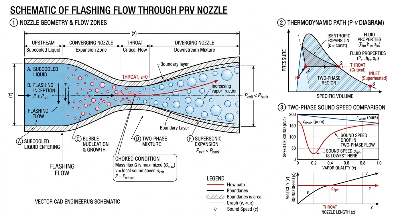
Two-Phase Flashing Flow through Relief Valve Nozzle and Speed of Sound Diagram


# 1. Fundamental Nozzle Flow Model (SI / MKS Units)

The mass flux (GoG_o) through an ideal, frictionless, isentropic relief valve nozzle is calculated by integrating Bernoulli's differential energy balance:

Go=ρnun=ρn2PoPndPρ(kg/(m2s))G_o = \rho_n u_n = \rho_n \sqrt{-2 \int_{P_o}^{P_n} \frac{dP}{\rho}} \quad (\text{kg}/(\text{m}^2\cdot\text{s}))

Where:

  • PoP_o = Stagnation pressure inside vessel (Pa absolute\text{Pa absolute})
  • PnP_n = Pressure at nozzle throat (Pa absolute\text{Pa absolute})
  • ρn\rho_n = Fluid density at nozzle throat (kg/m3\text{kg/m}^3)

The actual rated mass flow rate (WratedW_{rated}) incorporates the certified discharge coefficient (KdK_d) and ASME Code derating factor (0.900.90):

Wrated=0.90KdAnGo(kg/s)W_{rated} = 0.90 \, K_d \, A_n \, G_o \quad (\text{kg/s})

# 2. Single-Phase Flow Sizing Equations

# A. Incompressible Liquid Flow Sizing

For liquids with constant density (ρ=const\rho = \text{const}):

Go=2ρ(PoPb)G_o = \sqrt{2 \rho (P_o - P_b)}
W=AnKdKvKw2ρ(PoPb)(kg/s)W = A_n K_d K_v K_w \sqrt{2 \rho (P_o - P_b)} \quad (\text{kg/s})

Where: KvK_v is the viscosity correction factor for NRe<10,000N_{Re} < 10,000, KwK_w is the balanced bellows backpressure correction factor, and PbP_b is backpressure (Pa\text{Pa}).

# B. Compressible Gas / Vapor Flow Sizing (Ideal Gas Choked)

Choked flow occurs when fluid velocity at the nozzle throat reaches sonic velocity (un=cu_n = c). The critical pressure ratio ηc=Pc/Po\eta_c = P_c / P_o is:

ηc=(2k+1)kk1\eta_c = \left( \frac{2}{k+1} \right)^{\frac{k}{k-1}}

For choked gas flow (ηηc\eta \le \eta_c):

Gc=kPoρo(2k+1)k+1k1(kg/(m2s))G_c = \sqrt{k P_o \rho_o \left( \frac{2}{k+1} \right)^{\frac{k+1}{k-1}}} \quad (\text{kg}/(\text{m}^2\cdot\text{s}))
W=CKdAnPoMwZTo(kg/s)W = C \, K_d \, A_n \, P_o \sqrt{\frac{M_w}{Z T_o}} \quad (\text{kg/s})

Where (in SI units):

  • C=3.948k(2k+1)k+1k1C = 3.948 \sqrt{k \left(\frac{2}{k+1}\right)^{\frac{k+1}{k-1}}}
  • MwM_w = Molecular weight (kg/kmol\text{kg/kmol})
  • ToT_o = Stagnation temperature (K\text{K})
  • ZZ = Compressibility factor

# 3. Two-Phase Flashing Flow Sizing (DIERS Methodology)

When a boiling liquid or two-phase mixture relieves, static pressure drops along the nozzle path. Vapor flashes rapidly, expanding the mixture volume and reducing the speed of sound.

# Two-Phase Speed of Sound Phenomenon

The speed of sound in a homogeneous two-phase mixture (cc) drops dramatically below that of pure gas or liquid:

ccG=1k[ρG/ρLα(1α)]1/2\frac{c}{c_G} = \frac{1}{\sqrt{k}} \left[ \frac{\rho_G / \rho_L}{\alpha (1-\alpha)} \right]^{1/2}

Example: For a steam-water mixture at void fraction α=0.50\alpha = 0.50, where gas sound speed cG=500 m/sc_G = 500 \text{ m/s}, the two-phase sound speed drops to just 25 m/s25 \text{ m/s}! Consequently, two-phase mixtures choke at much higher backpressure ratios (ηc0.600.85\eta_c \approx 0.60 - 0.85) than pure gases (ηc0.53\eta_c \approx 0.53).

graph LR
    Vessel[Vessel Stagnation P_o, T_o] --> Nozzle[Relief Valve Nozzle]
    Nozzle --> Flash[Flashing / Vapor Generation]
    Flash --> Choke[Choked Flow at Throat P_c, G_c]
    Choke --> Exit[Discharge Pipe P_b]

# The Leung Omega (ω\omega) Method

The Omega method linearizes the two-phase density relationship relative to stagnation conditions:

ρoρ=ω(PoP1)+1\frac{\rho_o}{\rho} = \omega \left( \frac{P_o}{P} - 1 \right) + 1

# Calculating ω\omega for Saturated Flashing Fluids:

ω=αo(12Povfohfgo)+CpoToPovo(vfgohfgo)2\omega = \alpha_o \left( 1 - \frac{2 P_o v_{fo}}{h_{fgo}} \right) + \frac{C_{po} T_o P_o}{v_o} \left( \frac{v_{fgo}}{h_{fgo}} \right)^2

Where:

  • αo\alpha_o = Initial gas void fraction
  • vfov_{fo} = Liquid specific volume (m3/kg\text{m}^3/\text{kg})
  • vfgov_{fgo} = Specific volume change on vaporization (m3/kg\text{m}^3/\text{kg})
  • hfgoh_{fgo} = Latent heat of vaporization (J/kg\text{J/kg})
  • CpoC_{po} = Liquid heat capacity (J/(kgK)\text{J}/(\text{kg}\cdot\text{K}))

# Critical Pressure Ratio (ηc\eta_c) Determination:

Simpson explicit approximation (accurate to within 2%2\%):

ηc[1+(1.04460.0093431ω)ω0.56261]0.70356+0.014685lnω\eta_c \approx \left[ 1 + \left( 1.0446 - 0.0093431 \sqrt{\omega} \right) \omega^{-0.56261} \right]^{-0.70356 + 0.014685 \ln \omega}

# Choked Two-Phase Mass Flux (GcG_c):

Gc=ηcPoρoω(kg/(m2s))G_c = \eta_c \sqrt{\frac{P_o \rho_o}{\omega}} \quad (\text{kg}/(\text{m}^2\cdot\text{s}))

# 4. Worked Numerical Example (SI / MKS Units)

Scenario: Bottom relief of saturated liquid Ethylene at stagnation pressure Po=3.261 MPaP_o = 3.261 \text{ MPa} (32.61 bar32.61 \text{ bar}) and To=10.55CT_o = -10.55^\circ \text{C} (262.6 K262.6 \text{ K}).

  • Stagnation Properties:
    • ρL0=384.23 kg/m3\rho_{L0} = 384.23 \text{ kg/m}^3
    • vf0=0.002602 m3/kgv_{f0} = 0.002602 \text{ m}^3/\text{kg}
    • vfg0=0.012424 m3/kgv_{fg0} = 0.012424 \text{ m}^3/\text{kg}
    • hfg0=246,217 J/kgh_{fg0} = 246,217 \text{ J/kg}
    • CpL0=5,146 J/(kgK)C_{pL0} = 5,146 \text{ J}/(\text{kg}\cdot\text{K})
  1. Calculate Omega (ω\omega):
ω=CpL0ToPovL0(vfg0hfg0)2=(5146)(262.6)(3261000)0.002602(0.012424246217)2=4.25\omega = \frac{C_{pL0} T_o P_o}{v_{L0}} \left( \frac{v_{fg0}}{h_{fg0}} \right)^2 = \frac{(5146)(262.6)(3261000)}{0.002602} \left( \frac{0.012424}{246217} \right)^2 = 4.25
  1. Calculate Critical Pressure Ratio (ηc\eta_c):
ηc0.748    Pc=0.748×3.261 MPa=2.44 MPa (24.4 bar)\eta_c \approx 0.748 \implies P_c = 0.748 \times 3.261 \text{ MPa} = 2.44 \text{ MPa } (24.4 \text{ bar})
  1. Calculate Choked Mass Flux (GcG_c):
Gc=0.748(3,261,000)(384.23)4.25=12,835 kg/(m2s)G_c = 0.748 \sqrt{\frac{(3,261,000)(384.23)}{4.25}} = 12,835 \text{ kg}/(\text{m}^2\cdot\text{s})
  1. Calculate Valve Rated Capacity (WratedW_{rated}):
    With an effective orifice area An=1,186 mm2A_n = 1,186 \text{ mm}^2 (1.186×10³ m21.186 \times 10^{-3} \text{ m}^2) and Kd=0.975K_d = 0.975:
Wrated=0.90×0.975×(1.186×103)×12835=13.35 kg/s (48,060 kg/h)W_{rated} = 0.90 \times 0.975 \times (1.186 \times 10^{-3}) \times 12835 = 13.35 \text{ kg/s } (48,060 \text{ kg/h})

# ↔️ Series Navigation


Disclaimer: Two-phase relief sizing requires thermodynamic property verification. Use validated simulation tools like SuperChems or CCFlow for detailed design.

Process SafetyRelief Valve SizingTwo-Phase FlowLeung Omega MethodChoked Flow
Comments (0)

Discussion

Please Log In to participate in the technical discussion.

No comments posted yet. Be the first to share your input!