Part 1 of 6 in the Technical Series: Emergency Pressure Relief & Effluent Handling Systems
# Blog 1: Foundations of Overpressure Protection & International Safety Standards
In chemical manufacturing plants, oil refineries, and pharmaceutical synthesis facilities, controlling process pressure is the single most critical line of defense against catastrophic vessel failure. Emergency relief systems (ERS) are designed as the absolute last line of defense—they must function reliably and self-actuate under emergency conditions without reliance on external power, control instruments, or human operator intervention.
Historical incident data analyzed by process safety organizations shows that overpressure incidents result in devastating loss of life, facility destruction, and severe environmental contamination. In a landmark study of the 100 largest property losses in the hydrocarbon and chemical process industries over a 30-year period, fully one-quarter (25%) of all major losses were attributed directly to relief system inadequacy. In property damage alone, these incidents averaged ₹240 Crores (₹2.4 Billion / approx. 120 Million USD).
# 1. Regulatory & Industry Frameworks (RAGAGEP)
Engineers tasked with designing, auditing, or maintaining emergency pressure relief systems must strictly adhere to Recognized and Generally Accepted Good Engineering Practices (RAGAGEP). The primary regulatory mandates and consensus standards include:
# A. Regulatory Mandates
- OSHA PSM (29 CFR 1910.119): Occupational Safety and Health Administration standard governing Process Safety Management of Highly Hazardous Chemicals. Mandates complete documentation of Process Safety Information (PSI), initial Process Hazard Analysis (PHA), and periodic revalidation every 5 years.
- EPA RMP (40 CFR Part 68): Environmental Protection Agency Risk Management Plan rule focusing on off-site public protection, toxic dispersion prevention, and community safety.
# B. Codes and Consensus Standards
- ASME BPVC Section VIII, Division 1: The legal standard governing pressure vessels operating above ( / ). Sets design rules for overpressure protection, device certification, and vessel nameplate stamping.
- API Standard 520 (Parts I & II): American Petroleum Institute standards covering sizing, selection, and physical installation of pressure-relieving devices.
- API Standard 521: Extensive guidelines for evaluating causes of overpressure, calculating relief loads, establishing design bases, and selecting effluent disposal systems (flares, knockout drums, scrubbers).
- API Standard 526 & 527: Specifications for standard flanged steel PRVs and seat tightness testing standards.
- API Standard 2000: Venting requirements for atmospheric and low-pressure storage tanks ().
- NFPA Codes (NFPA 30, 15, 68, 69): Codes governing flammable liquid storage fire exposure, water spray protection, deflagration venting, and explosion prevention systems.
# 2. Key Terminology & Pressure Relationships
Understanding pressure relief requires strict adherence to standardized terminology:
graph TD
    A["Normal Operating Pressure (P_op <= 0.90 MAWP)"] -->|Operating Margin| B["Set Pressure (P_set <= MAWP)"]
    B -->|Overpressure| C["Relieving Pressure (P_rel)"]
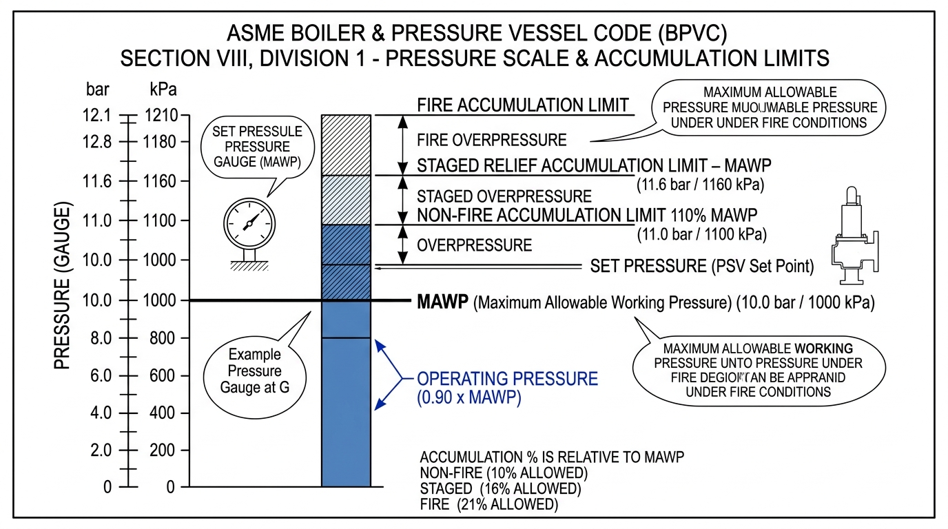
    MAWP["Vessel MAWP (1.00 MPa / 10.0 bar)"] -->|Allowable Accumulation| D["Maximum Venting Pressure"]
    C <= D
    D -->|Non-Fire Operating Upset| E["110% MAWP (1.10 MPa / 11.0 bar)"]
    D -->|Staged / Multiple Valves| F["116% MAWP (1.16 MPa / 11.6 bar)"]
    D -->|Fire Scenario| G["121% MAWP (1.21 MPa / 12.1 bar)"]
# Key Definitions (SI / MKS Units):
- MAWP (Maximum Allowable Working Pressure): The maximum gauge pressure permissible at the top of a vessel in its normal operating position at the designated operating temperature ( in or ).
- Design Pressure: The pressure specified on the vessel purchase order, used in structural design equations. The design pressure is equal to or less than the MAWP.
- Set Pressure (): The inlet static gauge pressure at which the relief device is adjusted to open under service conditions.
- Overpressure: The pressure increase over the set pressure of the relief valve during discharge, expressed as a percentage of set pressure ().
- Accumulation: The pressure increase over the MAWP of the vessel during discharge, expressed in pressure units ( or ) or as a percentage of MAWP ().
- Relieving Pressure (): The sum of set pressure plus overpressure ().
- Operating Margin: The difference between normal operating pressure and device set pressure. A margin of at least to is required to prevent seat leakage and valve simmer.
# 3. ASME Section VIII Accumulation Limits
ASME BPVC Section VIII Division 1 (paragraphs UG-125 through UG-140) sets explicit legal ceilings on maximum allowable venting pressure (accumulation) based on the upset contingency:
| Contingency Scenario | Single Relief Device Limit | Staged / Multiple Devices Limit | Standard Metric Example () |
|---|---|---|---|
| Non-Fire (Operating Upset) | of MAWP ( accumulation) | of MAWP ( accumulation) | |
| Fire Exposure Scenario | of MAWP ( accumulation) | of MAWP ( accumulation) | |
| Supplemental Liquefied Gas | of MAWP ( accumulation) | of MAWP ( accumulation) |
# 4. DIERS Benchmark Worked Example D.1.1: External Fire on Solvent Storage Vessel
To demonstrate the application of these rules, consider DIERS Benchmark Example D.1.1 from the book:
# A. Problem Statement & Given Conditions
A vertical cylindrical solvent storage tank with inside diameter () and straight-side height () with 2:1 elliptical heads has a volume ().
- Fluid Charge: Multicomponent solvent mixture ( Acetone, Ethanol, Water by weight). Initial fill level is ( at ).
- Vessel MAWP: ( / ).
- Fire Heat Input Rate (): Per NFPA 30 rules with approved drainage ( environmental factor), the heat input rate ().
- Relief Device: Conventional PRV set at ().
# B. Maximum Venting Pressure Calculation
For fire exposure under ASME Section VIII UG-125(c)(2), allowable accumulation is :
# C. Pure Component Physical Property Factor (PPF) Sizing Method
To determine the controlling component for relief sizing without complex flash thermodynamics, calculate the Physical Property Factor (PPF) for each component at :
| Component | Calculated | ||||||
|---|---|---|---|---|---|---|---|
| Water | |||||||
| Ethanol | |||||||
| Acetone |
Conclusion: Acetone yields the highest (), meaning it requires the largest vent area and dictates the design load!
# D. Required Relief Rate & Valve Orifice Selection
Using the controlling acetone vapor relief formula (accounting for liquid density expansion ratio):
Using API 526 standard orifice sizes with certified :
- Required Orifice Area: ().
- Selected PRV: 2J3 Valve (API orifice J with area / ).
- Rated Valve Capacity: (), providing ample capacity above the requirement!
# 5. Overpressure Protection by System Design (ASME UG-140 / HIPS)
Under ASME Code Case UG-140 and API 521 Annex E, a mechanical pressure relief valve may be resized or eliminated altogether if High Integrity Protection Systems (HIPS) or instrumented safety interlocks reduce the probability of an overpressurization event to an acceptably low level (typically ).
# ↔️ Series Navigation
- ➔ Next Article: Blog 2: Selecting Pressure Relief Devices & Managing Installation Constraints
- 📌 Series Overview & Roadmap: Mastering Pressure Relief & Effluent Handling
Disclaimer: Emergency pressure relief system design must strictly comply with current ASME BPVC Section VIII, API standards, and local environmental regulations.